ACEL
It is getting a bit old attaching, connecting, and replacing chips to a breadboard. Instead of using, say a 74LS08, which has AND gates, I want to use an Arduino Mega to act as an AND gate.
For example, I want to make pin 2 and pin 3 on the Mega to be inputs (A and B) of an AND gate and I want to make pin 4 to be the output (Q) of the AND gate.
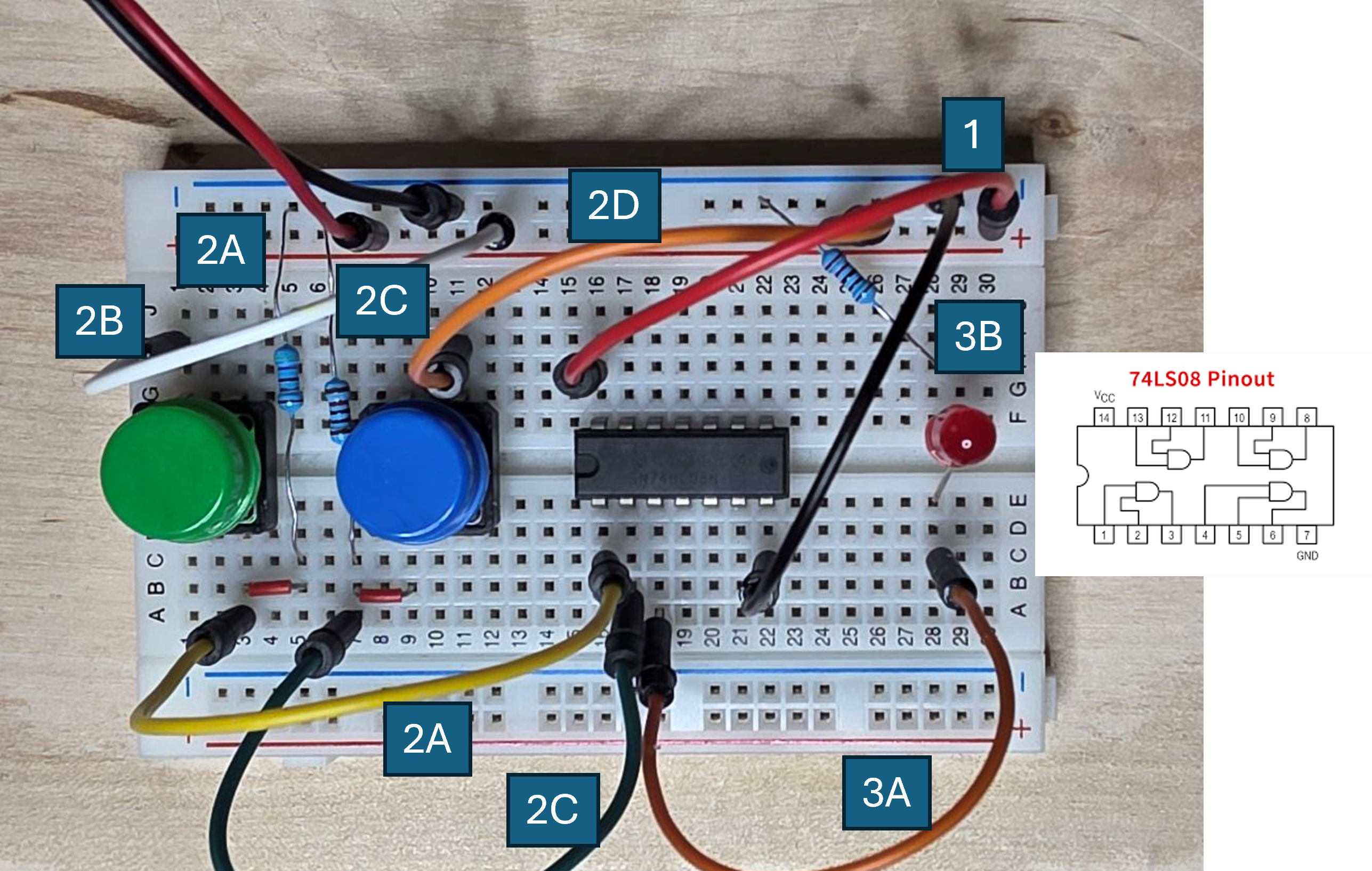
I can then replace the 74LS08 with an Arduino Mega. So instead of this
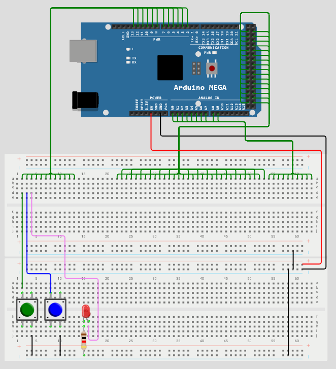
I do this:
Much cleaner and it works the same.
As long as I use the Arduino only to emulate basic logic gates, I do not feel that I am "cheating" in my goal of "building a computer from basic gates". It is still completely transparent and I can always replace the Arduino with physical chips if I like. It's just more convenient to use the Arduino. For example, if I want to physically replace the AND gate with an OR gate, I must replace the 74LS08 with the 74LS32. On the Arduino, I simply instruct it to be an OR gate. No rewiring necessary.
All of this can be done using ACEL (Arduino Chip Emulator Library). Here is the code to to make the Arduino into an AND gate:
If you want to replace the AND gate with an OR gate, all you need to do is to replace "AndGate()" with "OrGate()" under the section "Define chips".
You can play around with this yourself on Wokwi. Go to
https://wokwi.com/makers/jochumzen. Click the "Basic gates". This project has already been loaded with the ACEL and the code listed above. The Arduino Mega pins are connected to the upper breadboard in a way that corresponds to the numbers on the breadboard.
So an important thing to notice about the Arduino is that it has a built in pull-up resistor (not a pull-down).
Therefore, if you connect ground to a button and to an Arduino pin, the pin will be high when the button is released and low when it is pressed. Since it is more "natural" with the opposite, ACEL reverses the input signal, low to high and high to low. This way, you can simply connect ground to a button and to an Arduino pin and a pressed button will be "high".
Two buttons are connected to pin 2 and pin 3 (input A, B) to the AND gate making an input high when button is pressed. Pin 3 is connect to the LED. You actually do not need the current limiting resistor either if you use Wokwi - it does not care that it would be destroyed in an physical setup.
Start the simulation using the green play button. You can click on the buttons on the board to enable them. You can also enable them using your keyboard by pressing "1" or "2" (You may need to "click" on one of the buttons to make the keyboard shortcuts trigger). The LED turns on only when both buttons are enabled, in accordance with the AND gate.
You can stop the simulation and replace "AndGate" with "OrGate", "NandGate", or "NorGate", se entry 3. Start the simulation and confirm:
If you want to use a physical Mega and real buttons, LEDs and so on, you can download the library from Wokwi. You can then use the Arduino IDE or PlatformIO (these are the only ones I have tested). For more information about ACEL, check out the page on ACEL.