Decoder
In the previous entry, we concluded that we need an address decoder. Specifically, we need a 4-line to 16-line decoder:
The IC 74LS174 is a "4-Line to 16-Line Decoder/Demultiplexer". It has
- 4 inputs, labeled A, B, C, D
- inputs G1 and G2. G1 and G2 must both be low for decoding
- 16 outputs labeled 0 through 15
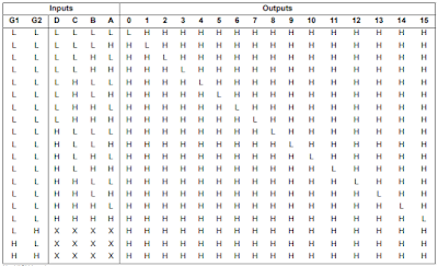
This is the function table of 74LS174:
Note that (when G1 and G2 are L) precisely one output pin is low, the rest are high.The 74LS174 can be designed from basic gates. Here is the logic diagram:
I designed this and named it Decoder4To16. It has
- 4 inputs, labeled D (D[0], D[1], D[2], D[3])
- An input E (Enable). E must be high for decoding
- 16 outputs labeled Q (Q[0] to Q[15])
This is the function table of Decoder4To16:
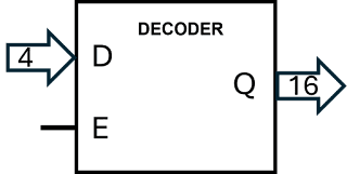
Note that (when E = 1) precisely one output pin is high, the rest are low. This is the symbol I will use for the 4-line to 16-line decoder:
Testing the decoder
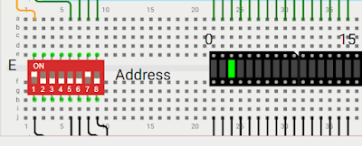
We can try this out using the following setup:
DIP 1 is connected to E (Enable) on the decoder and DIP 5-8 are connected to the input D. Sixteen LED's are connected to the output Q. In the picture, E=1 and the decoder is enabled. D = 0010, which is decimal 2. Therefore, Q2 is 1 (the rest are 0), as indicated by the LED. Try this out on Wokwi. The project name is "Address Decoder"
Here is the same physical setup with wires connected to the 4-line to 16-line decoder. Note that the two LED's to the left are unused (as well as the two on the right). The one which is on is the one with label "2".
Let's return to building a RAM.., in entry 18.


