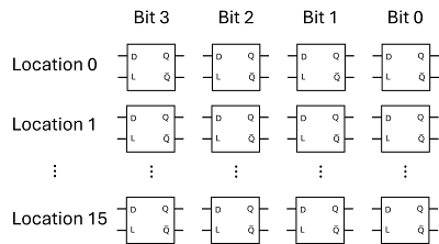
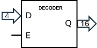
Let's continue building a 16x4 SRAM (from entry 16) now that we have the 4-line to 16-line decoder as well as D latches. This is where we left of:
Design Components
- Storage: 16 rows of 4-bit D latches (64 latches total).
- Address Decoder: Converts 4-bit address to 16 enable lines (1-of-16 selector).
- Control Logic: manage when we save data to RAM.
-tbc-
1. 64 D latches (see entry 16), in rows 0 to 15 and columns 0 to 3:
2. Address decoder (see entry 17)
Writing data to SRAM
This is what we are trying to achieve in this section:
- I have four data bits D3-D0, for example 0110 (decimal 6).
- I have four address bits A3-A0, for example 0011 (decimal 3).
- I want to store the data (6) att location/address 3; the 4 D latches at row 3 should contain 0110 after the save is complete.
- The rest of the D flip-flops should be left alone.
-cont:
Step-by-Step Design
1. Storage (16x4 D Latches)
- Latch Choice: Use D latch.
- For 16 rows × 4 bits, you’ll need 64 latches total.
- Connections per Row:
- D0–D3 (data inputs).
- Q0–Q3 (outputs).
-tbc-
So, for example, D3, the highest order data bit, should be connected to the D pin of all D latches in the Bit 3 column (and so on):
-cont:
2. Address Decoder (4-to-16)
- Purpose: Selects 1 of 16 rows based on A0–A3.
- Inputs: A0–A3 (4-bit address).
- Outputs: 16 lines (0–15, active low), each selecting one row.
- Wiring: Connect decoder outputs (Pins 1–16) to the "Load" of each row.
-tbc-
This makes sense. We connect the address A0-A3 (4 bit) to the decoder. We connect the output Q0 from the decoder to the "Load" (L) of the four D latches in row 0 (location 0 / address 0).
We connect Q1 from the decoder to L of the four D latches at address 1 and so on.
Now, if the address is, say 0011 (decimal 3), and the decoder is enabled (E = 1), then L = 1 for the 4 D flip-flops at address 3 (and 0 everywhere else). The 4 D latches at address 3 will store the data on D0-D3. The rest of the D latches will ignore the data.
When the decoder E = 0 (disabled), all L=0 and no data is latched. This should take care of "writing data to SRAM".
Reading data from SRAM
This is what we are trying to achieve in this section:
- I have four bits on the address bus A3-A0, for example 0011 (decimal 3).
- I want Q3-Q0 to be equal to the Q outputs of the four latches at location 3, 0110 in the picture below. Q3-Q0 are two-state output.
- I want W3-W0 to be the corresponding tri-state output, W = Q if three state switches are enabled, and W = Z otherwise.
-cont:
4. Data Output (Tri-State Outputs)
- Read Path: Each row’s Q0–Q3 outputs connect to a set of 4 tri-state buffers.
- 16 rows × 4 buffers = 64 buffers
- Buffer Inputs: Q0–Q3 from each row.
- Buffer Outputs: W0-W3
- Buffer Enable : Controlled by address decoder.
Row 0 of RAM:
When E0 = 1, the tri-state buffers are enabled, and W0-W3 is equal to Q0-Q3 of address 0.
Row/address 1 looks the same, but "Enable" is labeled E1. When E1 = 1, W0-W3 is equal to Q0-Q3 of address 1. In total, we have 16 tri-state "Enable" pins, E0..E15. At most 1 of them may be high.
Next, we connect a second 4-to-16 line decoder to the enable-lines E0-E15:
When this second decoder is enabled, and the address is, say 0011 (decimal 3), then E3 = 1, while the remaining buffers are disabled. W0-W3 becomes equal to Q0-Q3 at address 3. When this second decoder is disabled, then all E0..E15 are 0 and W = ZZZZ.
For the final step, we also want two-state output Q0-Q3, where Q0-Q3 are always the Q-outputs of the D latches at address D0-D3. This can be accomplished by a third 4-to-16 line decoder. This decoder is connected exactly like the second one, but the it is always enabled.
Summary
- Four input pins D3-D0 (data).
- Four input pins A3-A0 (address).
- Four output pins W3-W0 (tri-state output).
- Four output pins Q3-Q0 (two-state output).
- Input pin "Enable" of the first decoder (decoder to Load). When this E=1, data D3-D0 is written to RAM at address A3-A0. When this E=0, nothing is written to RAM.
- Input pin "Enable" of the second decoder (decoder to Enable Tri-state). When this E=1, W3-W0 is read from SRAM at address A3-A0. When this E=0, W3-W0 is ZZZZ (disconnected).
The ACEL chip "SixteenByFourRam" is designed precisely like this. Note that
- The "Enable" of the first decoder (decoder to Load) is denoted "Load" - it loads data into RAM.
- The "Enable" of the second decoder (decoder to Enable Tri-state) is denoted "Write" - it writes data to W3-W0.
Here is the symbol of SixteenByFourRam.
Testing
So to test SixteenByFourRam, let's connect 4 DIP-switches to D, 4 DIP-switches to A, buttons to Load and Write and Q to 4 LED's.
- DIP 1-4 is connected to A
- DIP 5-8 is connected to D
- Load: Loads the data D into address A
- Q is connected to LED's.
If you set an address on DIP 1-4, The LED's will display the value stored at this address. If you set some data on DIP 5-8 and click Load, this data is stored at the current address. W is tri-state and not connected, but you can check that W = ZZZZ unless you click "Write". Try this out on Wokwi, project "SRAM 16x4". Wokwi has a few steps for you to follow to better understand how the chip (as well as 74LS189) works.
Here is a physical setup:
Address is set to 0001 (or decimal 1) and the LED's show that 0011 (decimal 3) is stored at this address. Data is set to 0110 (decimal 6). If I click "Load", the data at address 1 will change to 0110 (decimal 6).
Next, we need to figure out how to connect the memory to the address and the data bus, ... in entry 19.


