In entry 24, we designed a T flip-flop, which functions as a 1 bit binary counter:
Making the 1 bit counter Loadable
The next step is to make it possible to "Load" a value into the counter. To do this, we use the Preset and Clear pins. Let's denote the value we want to load by "D":
- If we are loading the counter and D = 0, Clear should be 1 (and Preset = 0)
- If we are loading the counter and D = 1, Preset should be 1 (and Clear = 0)
- If we are not loading the counter, Preset and Clear should both be 0.
This is easy to do, no need to consult Grok:
Let's use the following symbol for the "loadable" T flip-flop:
To review:
- When L = 1, Q becomes equal to D (no clock involved)
- When L = 0, D is ignored. It then counts when T = 1 and Clock goes high.
4 bit counter
Let's look at the binary numbers between 0 and 3:
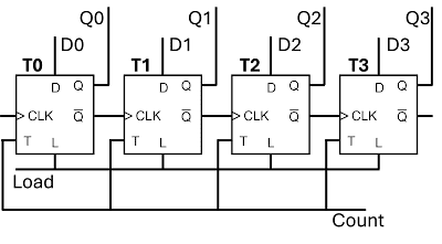
We use a T flip flop for the right-most binary digit (the lowest order), called T0. We also use a T flip-flop for the second binary digit from the right, called T1. However, T1 should only count when T0 becomes 0. This is easy to do: we simply connect Q-bar from T0 to the clock signal of T1. Now T1 will increment when T0 goes from 1 to 0, but not when it goes from 0 to 1.
Similarly, we use a T flip-flop for the third and the fourth binary digit from the right, T2 and T2. Q-bar from T1 is connected to the clock of T2, and Q-bar from T2 is connected to the clock of T3. This will result in a loadable 4 bit counter:
- It contains 4 T flip-flop, T0 to T3, holding binary digits Q0 to Q3. The four bit binary number is Q3_Q2_Q1_Q0.
- Input pin Clock. (goes to T0 clock)
- Input pin Count. When Count = 1, Q3_Q2_Q1_Q0 is incremented by 1 when clock goes high. When Count = 0, nothing happens when clock goes high.
- Input pin Load and input pins D0 to D3. When Load = 1, Q3_Q2_Q1_Q0 becomes equal to D3_D2_D1_D0. When Load = 0, D0 to D3 are ignored.
- Output pins Q0 to Q3. The count value hold by the counter. Note that Q0 is the lowest order bit and Q3 the highest.
Program counter
Two more issues before this is a program counter.
- The output (count) Q should be hooked up to the address bus. Therefore, we also need four tri-state switches hooked up to Q0-Q3 resulting in W0-W3, tri-state output. This also comes with a "Write" pin that enables the switches.
- A simpler way to set the count tp zero. It is already possible, by setting D0-D3 to 0000 and setting Load = 1. However, I want to add a control pin Clear, which when high, sets Q to 0. This is easy to do with an OR gate:
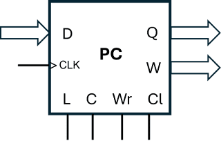
This is the symbol for my (for now) final program counter:
The name of this chip is "FourBitProgramCounter".
- D: four bits to set the count
- L: Load = 1 loads D
- C: Count = 1 will increase Q when Clock goes high
- Wr: Write = 1 enables tri-state, W = Q. When Write = 0, W = ZZZZ
- Cl: Clear = 1 sets Q = 0.
This chip is similar to 74LS193, the program counter suggested by Grok. Internally, they are designed differently. Also, 74LS193 can count downwards.
Testing the program counter
Here I have the "FourBitProgramCounter" in a Arduino Nano, together with a "SevenSegmentDecoderCathode", see entry 10. The clock signal from my 555 is connected to the Clock of the program counter. Count is set to 1 and the program counter Q is hooked up to the input pins of the decoder. I am not using any other pins on the counter. The output pins of the decoder are then connected to the display:
The green button is the "Print" button, printing the state of both the chips in the Nano.
You can try out the program counter on Wokwi as well ("Four bit program counter"). Here, you control the clock. In this project, Load and Clear are implemented. For example, you can try:
I want to hook up the program counter to the memory system... in the next entry.


