In entry 9, we designed a first version of a 4 bit register. Looking at the architecture of a simple CPU shows that registers are connected to an internal data bus.
Bus
Grok: A bus in electronics and computing is a set of shared electrical pathways (wires or traces) that multiple devices use to communicate data, addresses, or control signals within a system. Think of it as a highway where different components—like the CPU, memory, or registers—take turns sending or receiving information. It’s a key concept in a microprocessor. Let’s break it down.
What Is a Bus?
- Definition: A collection of parallel conductors (wires) that carry signals between components.
- Purpose: Simplifies connections—instead of wiring every device to every other device, they all connect to the bus and share it.
- Analogy: A bus is like a phone party line—everyone’s on the same line, but only one talks at a time.
Types of Buses
- Data Bus:
- Carries actual data (e.g., your 4-bit binary numbers).
- Width: Number of bits it handles at once.
- Bidirectional: Data flows both ways (e.g., memory to CPU or CPU to memory).
- Address Bus:
- Control Bus:
How a Bus Works
- Shared Lines: All devices connect to the same wires (e.g., 4 wires for a 4-bit data bus).
- Turn-Taking: Only one device drives the bus at a time to avoid conflicts (e.g., two devices outputting 0 and 1 simultaneously).
- Tri-State Outputs:
- Drive the bus (0 or 1) when enabled.
- Disconnect (Z) when not their turn, letting others take over.
-end-
Here is a nice picture of SAP-1, Simple as possible-1 "computer".
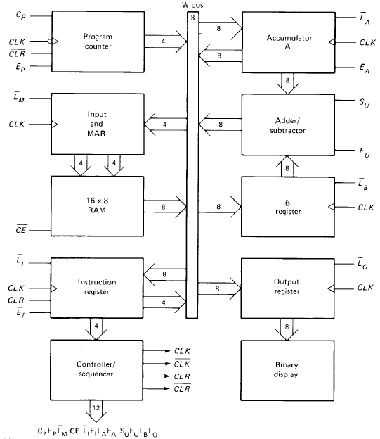
A bunch of "stuff" is connected to a bus, labeled "W bus", running along the middle of the image. This is a 8 bit bus, consisting of 8 wires. The arrows indicate if the component "puts data on the bus" or "reads data from the bus"
Register and Bus
The next question is how to "connect" my register to a bus. Groks curated answer:
Connecting your simple 4-bit register (built from four D flip-flops, like your setup) to a 4-bit data bus is straightforward, but there’s a catch: your register doesn’t have tri-state outputs natively, which are crucial for bus operation. Without tri-state capability, it will always drive the bus (Q outputs are always 0 or 1), potentially clashing with other devices. I’ll show you how to connect it as-is, then add a tri-state buffer to make it bus-friendly, tying it to your earlier projects. -end-
This makes sense. Each output pin of my register is always 0 or 1. Connecting two registers to the bus, like this, would not work:

Say that Q0 of register 1 is 1 (effectively connected to +5V) and Q0 of register 2 is 0 (effectively connected to ground), we would then have a direct connection from +5V to ground, a "short circuit". We need to make sure that at most one register is connected to the bus at one moment in time. Each output pin of a register should be either 0, 1, or "disconnected".
So, to make our register "bus-friendly", we must investigate the tri-state buffer. This is the next entry.
No comments:
Post a Comment